Spark Your Inner Maker: Easy Electronics Projects Await!
Want to build cool gadgets and learn practical electronics skills? This list of 8 beginner electronics projects offers a perfect starting point. From a simple LED blinker circuit to a more complex automatic plant watering system, you'll gain hands-on experience with circuits, sensors, and microcontrollers. These beginner electronics projects provide a foundation for understanding core concepts applicable to a wide range of electronics applications. Dive in and start creating!
1. LED Blinker Circuit
The LED blinker circuit is a cornerstone project for anyone entering the world of electronics. Often referred to as the "Hello World" of electronics, it provides a practical introduction to fundamental concepts like current flow, resistance, and basic circuit construction. This simple circuit makes an LED flash on and off at intervals determined by the circuit's design, offering immediate visual feedback and a satisfying sense of accomplishment for beginners. This project is a fantastic starting point for aspiring vibe coders, software developers, digital artists, educators, students, and hobbyists alike, offering a tangible entry into the world of hardware.
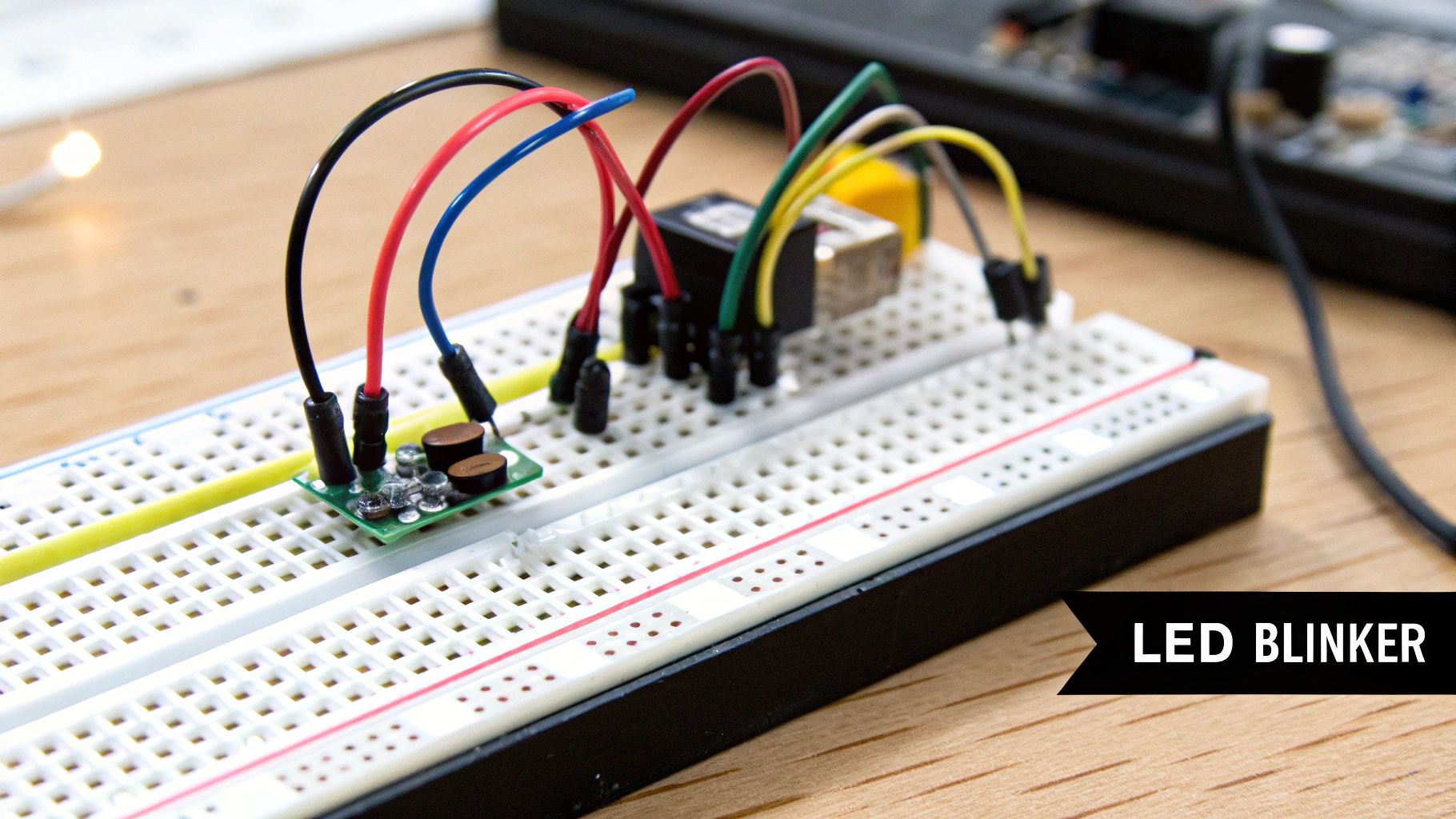
At its core, the LED blinker circuit utilizes a timing mechanism to control the flow of current to an LED. This timing mechanism can be achieved through several methods, the most common being the use of a 555 timer IC or an Arduino microcontroller. The 555 timer is a versatile integrated circuit capable of generating precise timing pulses, which can be used to switch the LED on and off. The Arduino microcontroller, a programmable platform popular among hobbyists and professionals, offers more flexibility in controlling the blinking pattern through software. In both cases, a resistor is used to limit the current flowing through the LED, preventing it from burning out.
This simple project can be implemented in several configurations, from a single LED flashing on and off to more complex setups involving multiple LEDs blinking in sequence or with varying brightness. The blink rate can be adjusted using variable resistors, allowing for customization and experimentation. Learn more about LED Blinker Circuit and find specific project examples. You might be surprised by the diverse applications, ranging from simple educational kits to more sophisticated projects. For instance, Arduino Uno provides a platform for beginners to explore LED blinker projects through its IDE and tutorials. The 555 timer-based LED flashers are commonly found in emergency lights, providing a reliable and easily implemented solution for visual signaling. Even DIY bicycle safety lights often utilize blinking LED circuits for increased visibility.
The LED blinker circuit offers several compelling advantages for beginners. Its simplicity translates to a low cost (typically under $5 in components) and minimal component requirements, making it accessible to almost anyone. The immediate visual feedback provides a clear indication of whether the circuit is functioning correctly, enhancing the learning process. Moreover, mastering the LED blinker circuit lays a strong foundation for more complex electronics projects.
While exceptionally beginner-friendly, the LED blinker circuit does have its limitations. Its practical applications, in its basic form, are somewhat limited. Those with prior electronics experience may find it too simplistic. Furthermore, the basic version doesn't introduce programming concepts, which are essential for more advanced projects. However, by utilizing a platform like Arduino, the project can be expanded to incorporate programming logic, thereby bridging this gap.
For those embarking on this project, several tips can ensure success. Accurately calculating the LED current limiting resistor is crucial to avoid damaging the LED. Starting with a breadboard allows for easy prototyping and adjustments before soldering a permanent circuit. Using a multimeter to verify voltages at each step can help identify and troubleshoot potential issues. Experimenting with different resistor values provides hands-on experience with how resistance affects the blink rate. Finally, documenting the circuit with a schematic drawing is a valuable practice for any electronics project.
The LED blinker circuit's enduring popularity can be attributed to influential figures and organizations in the electronics education space. The Arduino Foundation, through its IDE tutorials, has made the project accessible to a broad audience. Forrest Mims, a renowned author of electronics education books, has championed the LED blinker as a foundational learning tool. Publications like Make: Magazine have also played a significant role in popularizing the project through their beginner project guides, solidifying its place as a quintessential first step for aspiring electronics enthusiasts. It’s not just a project; it's the gateway to a fascinating world of electronics and a powerful demonstration of how simple circuits can bring ideas to life.
2. Simple Burglar Alarm
A simple burglar alarm is a fantastic beginner electronics project that offers a practical introduction to circuit design, sensor integration, and problem-solving. This project allows you to build a basic security system that detects intrusion and triggers an audible alarm. By combining various electronic components, you'll gain hands-on experience with real-world applications of electronics. This project is perfect for aspiring vibe coders, software developers looking to expand their hardware knowledge, and anyone interested in exploring the world of electronics.
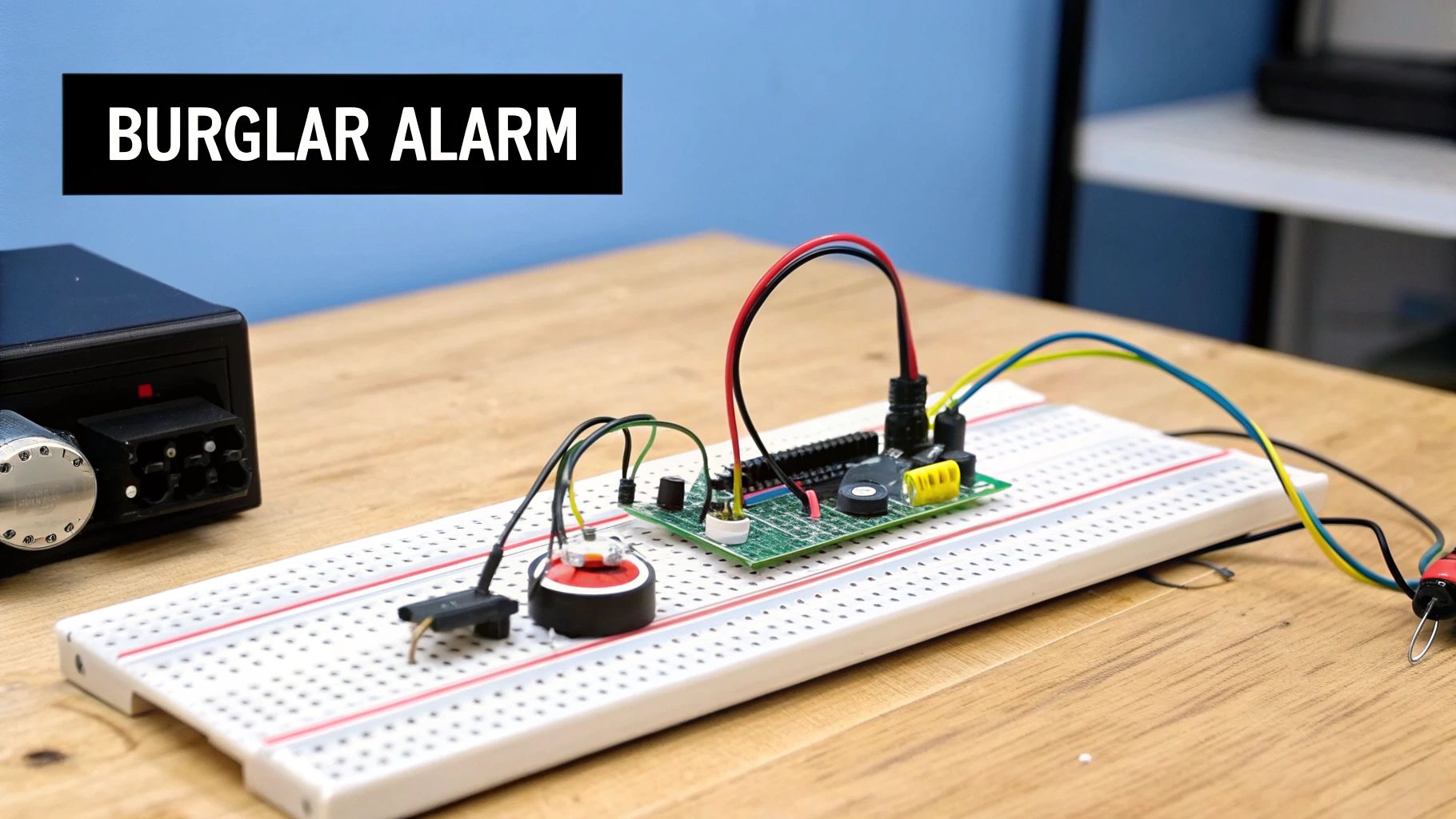
At its core, a simple burglar alarm consists of three main parts: a sensor, a control circuit, and an output device. The sensor detects the intrusion, whether it's a door opening, motion being detected, or a light beam being broken. This sensor then sends a signal to the control circuit. The control circuit acts as the "brains" of the operation. It receives the signal from the sensor and, based on its programming, activates the output device. The output device is typically a buzzer or siren that creates a loud noise to alert you to the intrusion.
This project deserves its place on the list of beginner electronics projects because it combines multiple electronic concepts in a practical and engaging way. It's more complex than single-component projects, offering a more challenging yet achievable learning experience. While simpler projects might introduce individual components, the burglar alarm integrates several, mirroring real-world electronics design.
A simple burglar alarm can be built using a variety of sensors. Magnetic reed switches are commonly used on doors and windows. When the door or window is opened, the magnet separates from the switch, triggering the alarm. Passive Infrared (PIR) motion detectors sense changes in heat signatures, activating the alarm when movement is detected. Light-dependent resistors (LDRs) can be used to create a light-beam break detector. When the beam is interrupted, the LDR's resistance changes, triggering the alarm.
Several features can be incorporated into your burglar alarm, including audible and visual alarm outputs, an arming/disarming switch, battery backup capabilities, and an expandable design for multiple zones. You can start with a basic setup and progressively add features as your skills develop. Learn more about Simple Burglar Alarm For example, instead of just a buzzer, you could add an LED that flashes when the alarm is triggered. You can find additional resources and project ideas online to help you customize your burglar alarm.
There are several advantages to building a simple burglar alarm as a beginner electronics project. It has a practical real-world application, teaching you how to interface sensors and design logic circuits. The project can be expanded with additional features, allowing you to continually learn and improve your skills. Furthermore, it's relatively inexpensive to build, making it accessible to beginners.
However, it’s important to be aware of the potential drawbacks. This project is more complex than single-component projects and requires an understanding of multiple circuit types. False alarms can be annoying during testing, and basic versions lack the advanced security features found in commercial systems. Proper sensor placement and sensitivity adjustment are crucial to minimize false alarms.
Here are some tips for building your simple burglar alarm:
- Start simple: Begin with a single sensor and a basic circuit before adding complexity. This allows you to understand the fundamental principles before moving on to more advanced features.
- Test mode: Include a test mode to avoid disturbing others while you're experimenting and calibrating the sensor sensitivity.
- Latching circuit: Use a latching circuit so the alarm remains active even after the initial trigger is removed, requiring a manual reset.
- Power consumption: If you're building a battery-operated version, consider power consumption to maximize battery life.
- Sensor positioning: Test sensor sensitivity and positioning thoroughly to minimize false alarms and ensure reliable detection.
The concept of the DIY burglar alarm has been around for decades, popularized by electronics hobby magazines of the 1970s and 80s, RadioShack project books, and, more recently, modern maker communities and YouTube channels. This project is a testament to the enduring appeal of learning electronics through practical, hands-on projects. This project is a great introduction to the world of "beginner electronics projects" and provides a solid foundation for future explorations in electronics.
3. Digital Thermometer
A digital thermometer is a fantastic beginner electronics project that bridges the gap between the physical world and your computer. It provides a practical introduction to microcontrollers, sensors, and programming, allowing you to build a useful device while learning fundamental electronics concepts. Unlike traditional analog thermometers, a digital thermometer uses electronic sensors to measure temperature and displays the reading on a digital display, offering greater precision and often additional features. This project is an excellent starting point for anyone interested in exploring the world of embedded systems and sensor interfacing. This project deserves its place on this list because it offers a tangible, real-world application of electronics principles, striking a good balance between complexity and accessibility for beginners.
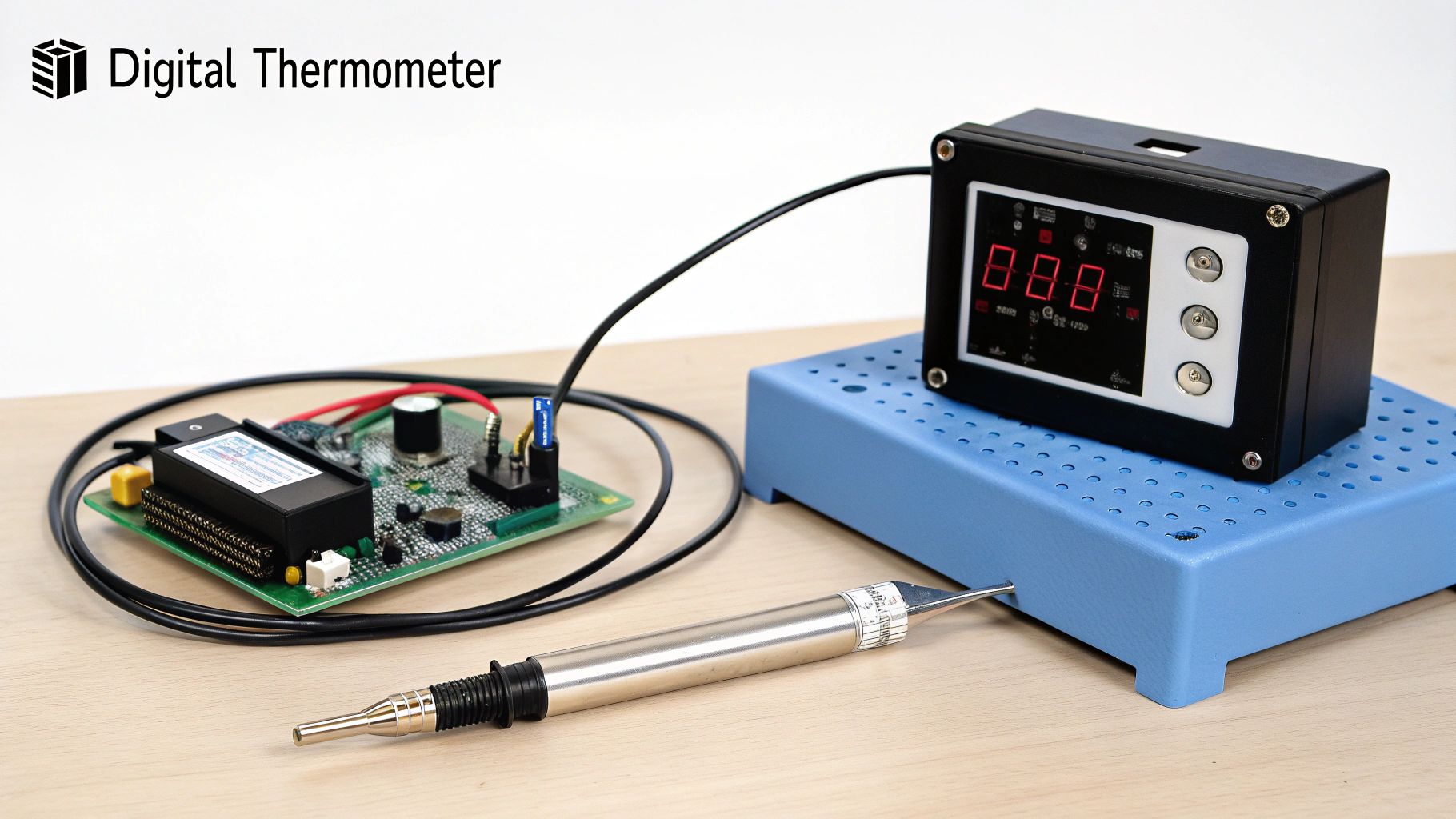
At the heart of a digital thermometer lies a temperature sensor. Popular choices for beginner projects include the LM35, DS18B20, and DHT22. The LM35 is an analog sensor, meaning it outputs a voltage proportional to the temperature. The DS18B20 and DHT22 are digital sensors, communicating temperature data directly to a microcontroller using a digital protocol. This data is then fed into a microcontroller, a small programmable computer like an Arduino. The microcontroller reads the sensor data, converts it into a readable temperature value (often involving analog-to-digital conversion for analog sensors), and displays it on a digital display. This display can be a simple LCD screen, a seven-segment LED display, or even sent to a computer for further processing and visualization.
The power of a digital thermometer project lies in its expandability and customizability. Beyond simply displaying the temperature, you can program the microcontroller to perform additional functions. For instance, you can log temperature data over time, trigger alarms when a specific temperature threshold is reached, or even control other devices based on the temperature reading. This makes it an ideal stepping stone for more complex projects like automated climate control systems or weather stations.
Examples of successful implementations range from simple Arduino-based room temperature monitors to sophisticated Raspberry Pi weather stations. In industrial settings, similar principles are applied for precise temperature monitoring in manufacturing processes. Even greenhouse climate control systems utilize digital temperature sensors to regulate the environment for optimal plant growth.
Pros:
- Practical Application: You build something useful for everyday life.
- Learning Opportunity: Introduces microcontroller programming, sensor interfacing, and analog-to-digital conversion.
- Expandable: Easily add features and integrate with other systems.
- Relatively Quick to Build: Provides a satisfying sense of accomplishment in a short time.
Cons:
- Programming Required: Microcontroller-based versions necessitate some coding knowledge.
- Sensor Calibration: Can be tricky for beginners, requiring careful attention to detail.
- Cost: Slightly more expensive than basic analog projects due to the microcontroller and display components.
Tips for Success:
- Calibration is Key: Calibrate your sensor against a known accurate thermometer to ensure reliable readings.
- Environmental Protection: Protect your sensors from moisture and extreme temperatures to maintain accuracy and longevity.
- Pull-up Resistors: Use pull-up resistors with digital temperature sensors like the DS18B20 for stable data transmission.
- Averaging for Stability: Implement temperature averaging in your code to smooth out fluctuations and provide more stable readings.
- Response Time: Consider the sensor's response time, especially for applications requiring rapid temperature changes.
Resources like Arduino community tutorials, Adafruit Industries sensor guides, and SparkFun Electronics educational materials provide excellent starting points and step-by-step instructions for building your own digital thermometer. By following these guides and applying the tips above, you’ll be well on your way to creating a functional and insightful beginner electronics project. This project provides a solid foundation in both hardware and software, empowering you to tackle more ambitious projects down the line. It's an excellent choice for aspiring vibe coders, experienced software developers looking to explore hardware, digital artists integrating physical computing into their work, educators teaching STEM concepts, and innovative hobbyists seeking practical applications of electronics.
4. Light-Following Robot
Building a light-following robot is an excellent beginner electronics project that bridges the gap between software and hardware, offering a tangible and engaging introduction to robotics, sensor integration, and basic artificial intelligence. This project secures its place on this list because it combines fun with learning, providing a visual and interactive demonstration of how simple circuits and code can create autonomous behavior. It's a perfect stepping stone for aspiring vibe coders, experienced software developers looking to delve into hardware, and anyone interested in exploring the fascinating world of robotics.
This project revolves around creating a small, self-navigating robot that seeks out and moves towards the brightest light source in its environment. The robot achieves this seemingly complex behavior through a relatively simple setup. At its core are photoresistors, also known as light-dependent resistors (LDRs). These sensors change their resistance based on the intensity of light falling on them. The robot typically uses two or more LDRs, strategically positioned to allow it to determine the direction of the strongest light source. The difference in resistance between the sensors provides the necessary information for the robot to orient itself.
The “brains” of the operation is a microcontroller, a small programmable computer chip. The microcontroller reads the analog values from the LDRs, representing the light intensity. Based on these readings, it decides which direction to move. This decision-making process is a simple form of artificial intelligence, where the robot reacts to environmental stimuli (light) and adjusts its behavior accordingly. The microcontroller then sends signals to the motors, controlling their speed and direction.
Most light-following robots employ a differential drive system, meaning they have two independently controlled motors. By varying the speed of each motor, the robot can turn and move in any direction. For instance, if the right LDR detects more light, the microcontroller might slow down the right motor and speed up the left motor, causing the robot to turn right towards the brighter light.
The features of a light-following robot can be quite diverse. Beyond basic light-seeking, many incorporate obstacle avoidance capabilities using additional sensors, such as ultrasonic range finders or infrared sensors. Adjustable light sensitivity thresholds allow customization of the robot’s behavior, enabling it to respond to different light levels. Learn more about Light-Following Robot
Pros:
- Engaging combination of programming and hardware: This project is an ideal blend of coding and electronics, offering a hands-on learning experience for both software and hardware enthusiasts.
- Visual demonstration of sensor-based control: The robot's behavior visually demonstrates the principles of sensor integration and feedback loops, making complex concepts easier to understand.
- Foundation for more advanced robotics projects: The skills learned from building a light-following robot provide a solid base for tackling more sophisticated robotics endeavors.
Cons:
- Requires both electronics and mechanical skills: Building the robot involves soldering, wiring, and potentially some mechanical assembly, requiring a broader skillset than purely software-based projects.
- More expensive due to motors and chassis requirements: The need for motors, a chassis, and potentially other mechanical components adds to the overall cost of the project.
- Troubleshooting can be complex with multiple systems: Debugging issues that arise from the interplay of mechanical, electronic, and software components can sometimes be challenging.
Tips for Building a Light-Following Robot:
- Start simple: Begin with a basic two-wheel design to grasp the fundamental concepts before adding complexity.
- Test independently: Test your sensors and motors individually before integrating them into the complete system to isolate potential problems early on.
- Use PWM: Implement Pulse Width Modulation (PWM) to control the motor speed smoothly and efficiently.
- Shield sensors: Shield your light sensors from the shadows cast by the robot itself to prevent inaccurate readings.
- Implement hysteresis: Introduce hysteresis in your code to prevent the robot from oscillating between two light sources of similar intensity.
The light-following robot project has a rich history, popularized by the BEAM robotics movement in the 1990s, spearheaded by Mark Tilden. Educational programs like VEX Robotics and vibrant online communities like the Arduino robotics community have further cemented its place as a classic beginner electronics project. Examples of successful implementation range from educational robotics kits for schools to solar panel sun-tracking systems and even automated greenhouse plant-following systems. This project not only offers a fun and educational experience but also serves as a gateway to the exciting possibilities of robotics and artificial intelligence.
5. Touch-Sensitive Lamp
This project offers a fantastic introduction to the world of capacitive touch sensing, a technology ubiquitous in modern devices from smartphones to kitchen appliances. Building a touch-sensitive lamp is a rewarding beginner electronics project that blends hardware and software principles while resulting in a practical and stylish creation. This project deserves its place on the list because it bridges the gap between basic circuitry and more advanced concepts like sensor integration and microcontroller programming. It's a perfect stepping stone for those looking to expand their electronics skills beyond simple LED circuits and delve into the realm of human-computer interaction.
The core concept behind a touch-sensitive lamp revolves around detecting changes in capacitance caused by the proximity or touch of a human finger. Capacitance is the ability of a system to store an electrical charge. A touch sensor, essentially a capacitor, is formed by two conductive plates separated by a dielectric material (often air or a thin insulator). When you touch the sensor, your body acts as another conductive plate, effectively increasing the capacitance of the system. This change in capacitance is detected by a dedicated touch sensor IC (like the TTP223) or a microcontroller with capacitive sensing capabilities. The detected change then triggers an action, such as turning on an LED, changing its brightness, or activating a relay to control an AC-powered lamp.
This project offers several compelling features. Touch activation eliminates the need for mechanical switches, resulting in a sleek, modern aesthetic and increased durability. Many designs incorporate multiple brightness levels, allowing users to cycle through different intensities with sequential touches. Perhaps most impressively, capacitive sensing can work through non-conductive materials like glass, plastic, or even thin wood, opening up exciting design possibilities. You can even incorporate color-changing LEDs for added visual flair. Furthermore, a memory function can be implemented to store the last brightness setting, enhancing user convenience.
Examples of successful implementations:
- Commercial touch-sensitive table lamps: These are readily available in various styles and price points, demonstrating the widespread adoption of this technology.
- Capacitive touch light switches: These modern wall switches offer a sleek alternative to traditional mechanical switches and often integrate dimming functionality.
- Interactive art installations: Artists utilize capacitive touch sensing to create engaging and responsive installations that react to the audience's touch.
- Smart home lighting systems: Many smart lighting systems incorporate touch-sensitive controls, allowing users to adjust lighting directly on the fixture or through a central hub.
Pros:
- Modern, intuitive user interface
- No mechanical parts to wear out
- Can work through glass, plastic, or wood surfaces
- Impressive demonstration of capacitive sensing
- Practical home improvement application
Cons:
- More complex than simple switch-based circuits
- Sensitivity can be affected by humidity and temperature
- AC power control requires safety precautions
- May require EMI filtering for reliable operation
Tips for Building Your Own Touch-Sensitive Lamp:
- Start with low-voltage LEDs: Gain experience with the basic principles of capacitive sensing and microcontroller programming before working with potentially dangerous AC voltages. This allows you to focus on the touch sensing aspect without the added complexity and safety concerns of mains voltage.
- Safety First with AC: If you choose to work with AC power, exercise extreme caution. Use appropriate safety measures, including isolation transformers and insulated tools. Incorrect handling of mains voltage can be lethal.
- Experiment with Touch Pad Size and Placement: The size and placement of the conductive touch pad significantly influence the sensor's sensitivity and performance. Experiment with different configurations to optimize the user experience.
- Debouncing is Crucial: Debouncing techniques, either in hardware or software, are essential to prevent false triggers caused by electrical noise or multiple sensor activations from a single touch.
- Optoisolators for Safety: Consider using optoisolators (optocouplers) for AC power control. These devices provide electrical isolation between the low-voltage control circuit and the high-voltage AC circuit, enhancing safety.
Getting Started: Numerous resources are available online, including DIY electronics YouTube channels and online forums dedicated to Arduino and other microcontrollers, offering detailed tutorials and code examples for building your own touch-sensitive lamp. These communities provide a wealth of information for beginners, allowing you to learn from others’ experiences and troubleshoot any issues you encounter. This project is a great way to delve into the world of beginner electronics projects, offering both practical application and a satisfying learning experience. From understanding fundamental electronics principles to exploring advanced concepts like sensor interfacing, the touch-sensitive lamp project is a valuable addition to any aspiring electronics enthusiast's repertoire.
This project is popularized by advancements in capacitive touch technology, starting from patents in the 1960s, significantly boosted by modern smartphone touch interface development, and further disseminated through DIY electronics communities and smart home enthusiasts.
6. FM Radio Receiver
Building an FM radio receiver is a classic and rewarding beginner electronics project that provides a fascinating introduction to the world of radio frequency (RF) communication. This project allows you to delve into the principles of electromagnetic waves, signal processing, and audio amplification, culminating in a functional device that can tune into your favorite radio stations. It's a fantastic addition to any list of beginner electronics projects because it bridges the gap between basic circuit theory and more advanced high-frequency concepts, offering a practical and engaging learning experience. This project deserves its place on this list due to its educational value, the tangible result of a working radio, and its potential for customization and expansion.
At its core, an FM radio receiver captures radio waves transmitted by FM broadcast stations and converts them back into audible sound. These radio waves are electromagnetic waves that carry information encoded in variations of their frequency, a process known as frequency modulation (FM). The receiver utilizes specialized integrated circuits (ICs) to perform this intricate task. Chips like the TDA7000 were popular choices in earlier designs, but more modern and feature-rich ICs like the TEA5767 are readily available today, simplifying the design and offering improved performance. These chips handle the complex processes of RF amplification, filtering, demodulation, and audio amplification, making the project accessible to beginners.
The process begins with an antenna, which captures the electromagnetic waves. The signal is then amplified and filtered to select the desired frequency band (88-108 MHz for FM broadcast). The heart of the receiver, the demodulator, extracts the audio signal from the modulated RF carrier wave. This audio signal is then amplified and fed to a speaker, allowing you to hear the broadcast.
Several key features contribute to the functionality of the FM radio receiver:
- Receives FM Broadcast Band (88-108 MHz): This covers the standard frequency range used by FM radio stations worldwide.
- Variable Frequency Tuning: Allows you to select different radio stations within the FM broadcast band. This is typically achieved with a variable capacitor or a digitally controlled tuning mechanism.
- Audio Amplification and Speaker Output: Amplifies the demodulated audio signal to a level suitable for driving a speaker.
- Antenna Input for Signal Reception: Provides a connection point for an external antenna to improve signal reception.
- Optional Digital Frequency Display: Adds a visual display of the tuned frequency, enhancing the user experience.
Pros of building an FM Radio Receiver:
- Teaches RF and Communication Principles: Provides a hands-on understanding of radio frequency circuits and how information is transmitted wirelessly.
- Results in a Practical, Usable Device: You end up with a working radio that you can use to listen to your favorite stations.
- Introduction to High-Frequency Circuit Design: Exposes beginners to the unique challenges and techniques involved in designing circuits operating at higher frequencies.
- Demonstrates Electromagnetic Wave Principles: Reinforces the concepts of electromagnetic waves and how they are used for communication.
- Can be Enhanced with Digital Features: Allows for customization and the addition of features like digital tuning and frequency display.
Cons of building an FM Radio Receiver:
- RF Circuits can be Sensitive to Layout and Interference: Proper circuit layout and grounding techniques are crucial to avoid unwanted noise and interference.
- Requires Understanding of Higher-Frequency Concepts: While beginner-friendly, a basic grasp of concepts like impedance matching and filtering is beneficial.
- Antenna Design and Positioning Affects Performance: The type and placement of the antenna can significantly impact the receiver's sensitivity and ability to capture signals.
- More Complex Troubleshooting than DC Circuits: Debugging RF circuits can be more challenging due to the invisible nature of radio waves.
Examples of FM Radio Receiver Implementations:
- Portable Transistor Radios: Classic examples of compact FM receivers.
- Car Radio Systems: More complex systems often incorporating additional features like RDS (Radio Data System).
- Software-Defined Radio (SDR) Projects: Computer-based radio receivers that offer advanced capabilities and flexibility.
- Emergency Weather Radio Systems: Dedicated receivers for receiving weather alerts and broadcasts.
Tips for Building an FM Radio Receiver:
- Use Proper RF Circuit Layout Techniques: Keep signal traces short and direct to minimize signal loss and interference.
- Keep Antenna Leads Short and Direct: Longer antenna leads can introduce noise and reduce signal strength.
- Use Shielding to Prevent Interference: Enclosing the circuit in a metal case can help reduce interference from external sources.
- Test in Areas with Strong FM Signals Initially: This simplifies troubleshooting and ensures the receiver is functioning correctly.
- Consider Using Pre-made RF Modules for Easier Construction: Modules like the TEA5767 simplify the design process and reduce the complexity of the circuit.
Building an FM radio receiver is a rewarding experience that offers a practical application of electronics principles. By following these tips and understanding the underlying concepts, even beginners can successfully build a functioning radio and gain valuable experience in the exciting world of RF electronics. This project is a stepping stone for exploring more advanced concepts in communication systems and digital signal processing, laying a strong foundation for future electronics projects.
7. Automatic Plant Watering System
Building an automatic plant watering system is a fantastic beginner electronics project that bridges the gap between software and the physical world. It allows you to delve into the world of embedded systems while solving a practical problem – keeping your plants perfectly hydrated. This project offers a rewarding blend of hardware and software, making it ideal for aspiring vibe coders, experienced software developers looking to explore hardware, and anyone interested in building smart home solutions. By monitoring soil moisture and automatically activating a water pump, you create a miniature ecosystem that responds to its environment. This project epitomizes the spirit of beginner electronics projects, offering a tangible, functional outcome that introduces key concepts in a fun and engaging way.
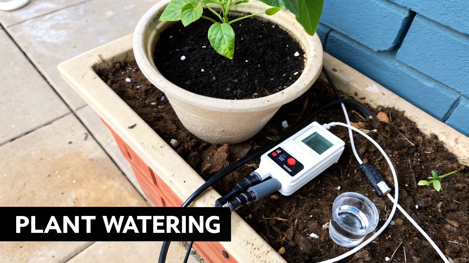
At its core, this project revolves around a soil moisture sensor. This sensor acts as the system's eyes, constantly measuring the water content in the soil. The sensor's readings are then fed into a microcontroller, the brains of the operation. The microcontroller compares the moisture level to a pre-defined threshold. If the moisture level falls below this threshold, signaling dry soil, the microcontroller activates a water pump, delivering water to the plants. Once the soil reaches optimal moisture levels, the pump is deactivated. This simple yet effective feedback loop forms the foundation of an automatic watering system.
Several successful implementations of this concept exist, ranging from simple DIY setups to sophisticated commercial products. Commercial drip irrigation controllers automate watering for large-scale agricultural operations. Smart garden systems like Click & Grow offer compact, self-contained units for indoor gardening. Even complex greenhouse automation systems employ similar principles to maintain optimal growing conditions. These examples demonstrate the scalability and versatility of automated plant watering systems, making it a relevant project for anyone interested in electronics, from hobbyists to aspiring entrepreneurs.
This project offers several advantages for beginners. It teaches valuable skills in sensor calibration, threshold detection, and automated control systems. You'll learn how analog sensors work, how to translate their readings into actionable data, and how to control outputs based on these readings. The project is also highly expandable. You can start with a single plant and gradually increase complexity by adding multiple plant zones, each with its own sensor and watering schedule. You could even integrate wireless monitoring and control via Wi-Fi or Bluetooth, turning your project into a fully-fledged IoT device, perfect for demonstrating IoT concepts to educators and students in tech.
However, there are a few challenges to be aware of. Working with water and electronics necessitates careful consideration of safety. Waterproof all electrical connections and use food-grade tubing for water delivery. Pump selection can be crucial, depending on the water pressure and flow rate required. Sensor corrosion and maintenance can also be an issue, particularly with long-term deployments. Implementing failsafes, like a manual override or a timer to prevent overwatering, is crucial to avoid potential damage to the plants and the system itself.
For those embarking on this project, here are some actionable tips:
- Waterproof everything: This is paramount. Enclose all electronic components in waterproof enclosures and ensure all connections are sealed.
- Calibrate your sensors: Different soil types retain water differently. Calibrate your moisture sensors for the specific soil you're using to ensure accurate readings.
- Manual override: Always include a manual override switch to control the pump independently, allowing you to intervene if needed.
- Food-grade tubing: Use food-grade tubing for water delivery to prevent contamination and ensure plant health.
- Failsafes: Implement a timer or a secondary moisture sensor as a failsafe to prevent overwatering.
The automatic plant watering system is an excellent beginner electronics project because it combines practical application with valuable learning opportunities. It provides a solid foundation in fundamental electronics concepts while allowing for creative expansion and customization. Whether you're a seasoned coder looking to explore the physical world or a complete beginner eager to build something useful, this project offers a rewarding and enriching experience. It's no wonder this project has been popularized by various communities, from agricultural automation to smart home enthusiasts and sustainable gardening movements. So, grab your components, roll up your sleeves, and embark on this exciting journey into the world of automated plant care.
8. Digital Clock with Alarm
Building a digital clock with alarm functionality is an excellent beginner electronics project that bridges the gap between simple circuits and more complex, interactive devices. This project provides a practical introduction to several core electronics concepts, making it a rewarding experience for aspiring makers and a valuable addition to any beginner electronics project list. By combining hardware and software, you'll create a functional timepiece that can be customized and expanded upon in numerous ways. This project is particularly beneficial for those looking to delve into real-time programming and user interface design within the context of a tangible, everyday object.
At the heart of this project lies the real-time clock (RTC) module, typically the DS3231. This integrated circuit maintains accurate timekeeping even when the main power is off, thanks to a small backup battery. The RTC communicates with a microcontroller, which acts as the brains of the operation. Popular choices for microcontrollers include the Arduino Uno, Nano, or ESP32, offering varying levels of processing power and features for different project complexities. The microcontroller reads the time data from the RTC, processes it, and then displays it on a chosen output device. The most common output for beginners is a multi-digit 7-segment LED display. These displays are relatively easy to interface with and provide a clear, digital readout of the time. Alternatively, you can use an LCD screen for a more sophisticated interface, capable of displaying more information like the date or even custom messages.
The alarm functionality is implemented through the microcontroller's interrupt system. The RTC can be programmed to trigger an interrupt at a specific time, which wakes up the microcontroller and initiates the alarm sequence. This might involve activating a buzzer, blinking the display, or even triggering a relay to control an external device. This introduces the concept of event-driven programming, an essential aspect of embedded systems development.
This project allows for several custom features, such as a snooze function, 12/24 hour format selection, and even multiple alarm settings. More advanced features like automatic brightness control based on ambient light or synchronization with internet time servers can also be incorporated. The possibilities for customization make this project a great platform for learning and experimentation, allowing you to tailor the final product to your specific needs and preferences.
Examples of Successful Implementation:
This project isn't just a learning exercise; it has practical applications. Digital clocks with alarm functionality are ubiquitous in our daily lives:
- Bedside Digital Alarm Clocks: The classic example, waking us up each morning.
- Microwave and Appliance Time Displays: Integrating timekeeping into everyday appliances.
- Car Dashboard Clocks: Providing drivers with accurate time information.
- Computer and Smartphone Time Displays: Although more complex, these are based on the same fundamental principles.
Actionable Tips for Readers Embarking on This Beginner Electronics Project:
- Use a Dedicated RTC Chip: Chips like the DS3231 offer significantly better timekeeping accuracy than relying solely on the microcontroller's internal clock.
- Implement Proper Button Debouncing: This prevents spurious readings from button presses, ensuring reliable user input for setting the time and alarm.
- Consider Display Brightness: Implement brightness control, either manually or automatically, for comfortable viewing in different lighting conditions, especially at night.
- Include Backup Battery for Settings Retention: A small coin cell battery ensures that the time and alarm settings are preserved even when the main power is disconnected.
- Plan the User Interface Flow Before Programming: Mapping out how the user will interact with the clock simplifies the coding process and results in a more intuitive user experience.
Pros and Cons:
Pros:
- Highly Practical Everyday Device: You end up with a functional clock you can actually use.
- Teaches Real-Time Programming Concepts: A great introduction to interrupts and event-driven programming.
- Combines Multiple Interface Elements: You’ll learn how to integrate different components like displays, buttons, and buzzers.
- Good Introduction to User Interface Design: You'll gain experience in creating a user-friendly interface.
- Can be Enhanced with Many Additional Features: This project offers plenty of room for customization and expansion.
Cons:
- Requires Programming Skills for Full Functionality: You’ll need some basic programming knowledge to control the microcontroller.
- Multiple Components Increase Complexity: Managing the connections and interactions between different components can be challenging for beginners.
- Accurate Timekeeping Requires Quality RTC Modules: Choosing a reliable RTC chip is crucial for accurate timekeeping.
- User Interface Programming Can Be Challenging: Designing a smooth and intuitive user interface requires careful planning and implementation.
This project firmly deserves its place on the list of beginner electronics projects because it offers a balanced mix of practical application, learning opportunities, and customization potential. While requiring some basic programming skills, the project's clear objectives and readily available resources make it an achievable and rewarding experience for those venturing into the world of electronics. It's a stepping stone towards more complex projects and provides a solid foundation in essential concepts like real-time programming and user interface design.
Beginner Electronics Project Comparison
| Project Title | Implementation Complexity 🔄 | Resource Requirements ⚡ | Expected Outcomes 📊 | Ideal Use Cases 💡 | Key Advantages ⭐ |
|---|---|---|---|---|---|
| LED Blinker Circuit | Very low (Beginner) | Minimal components, low cost | Basic electronics understanding | Electronics beginners, education | Simple, low cost, immediate feedback |
| Simple Burglar Alarm | Low to intermediate | Multiple sensors and output devices | Basic security system | Home security, sensor integration | Practical, expandable, multi-concept |
| Digital Thermometer | Intermediate | Microcontroller, sensors, display | Accurate temperature readings | Weather monitoring, industrial use | Practical, programmable, sensor-based |
| Light-Following Robot | Intermediate | Motors, chassis, sensors, microcontroller | Autonomous light tracking robot | Robotics education, competitions | Engaging, combines mechanics & electronics |
| Touch-Sensitive Lamp | Intermediate | Touch sensor IC, power control parts | Intuitive touch control lighting | Smart home, interactive lighting | Modern UI, no mechanical wear |
| FM Radio Receiver | Intermediate to advanced | Specialized RF components | FM radio reception and audio output | Communication projects, hobbyist radios | Practical device, teaches RF concepts |
| Automatic Plant Watering System | Intermediate | Sensors, pump, tubing, microcontroller | Automated irrigation control | Gardening, greenhouse automation | Practical, scalable, IoT integration |
| Digital Clock with Alarm | Intermediate | RTC module, microcontroller, display | Accurate timekeeping with alarms | Everyday device, embedded systems | Practical, multiple features |
Level Up Your Electronics Skills
This collection of 8 beginner electronics projects, ranging from a simple LED blinker circuit to a more complex automatic plant watering system, offers a practical and engaging introduction to the world of electronics. By successfully completing these projects, you’ll gain a foundational understanding of core concepts like circuits, resistors, capacitors, and microcontrollers. The most important takeaways include understanding circuit diagrams, using a breadboard, and troubleshooting common issues—essential skills for any aspiring electronics enthusiast.
Mastering these beginner electronics projects is more than just assembling components; it’s about cultivating a problem-solving mindset and building a strong foundation for future learning. Whether you're a Vibe coder looking to integrate hardware into your projects, an experienced software developer branching into the physical world, a digital artist exploring interactive installations, or simply a curious hobbyist, these projects will equip you with the practical skills and confidence to bring your ideas to life.
For those eager to delve deeper, platforms like Vibecoding VIP offer a wealth of resources, including advanced tutorials, coding examples, and a supportive community to help you on your journey. Building upon these beginner electronics projects opens doors to a vast landscape of possibilities. You can explore more complex projects like robotics, IoT devices, and even wearable technology. The world of electronics is ripe with opportunity for innovation – keep experimenting, keep learning, and most importantly, keep creating! Your next breakthrough could be just a circuit away.